 | EVALUATION OF COMPATIBILITY AMONG NETWORK ADJUSTMENT APPLICATIONS |
Conservatoire national des arts et métiers (Cnam), European Organization for Nuclear Research (CERN), and School of Management and Engineering Vaud (HEIG-VD) are three institutions that have developed their own network adjustment applications: Compensation de Mesures Topographiques (CoMeT), Logiciel Général de Compensation (LGC), and Trinet+, respectively.
In all these applications, three-dimensional mathematical functional models are used to process observations. However, some discrepancies may exist in the obtained results between these applications due to differences in the implementation of the functional models.
Since 2017, we are working together to study the compatibility and the interoperability between our network adjustment tools. In 2020, a common research paper was published in the Journal of Surveying Engineering:
Durand Stéphane, Touzé Thomas, Jones Mark, Guillaume Sébastien, Cattin Paul-Henri, Morel Laurent Evaluation of Compatibility among Network Adjustment Software: CoMeT, LGC, and Trinet+ Journal of Surveying Engineering Volume 146 - Issue 2 - May 2020 https://doi.org/10.1061/(ASCE)SU.1943-5428.0000304
We are also working in order to include other commercial or free network adjustement applications in our tests.
This page contains some informations about this work, which is still in progress.
Network design
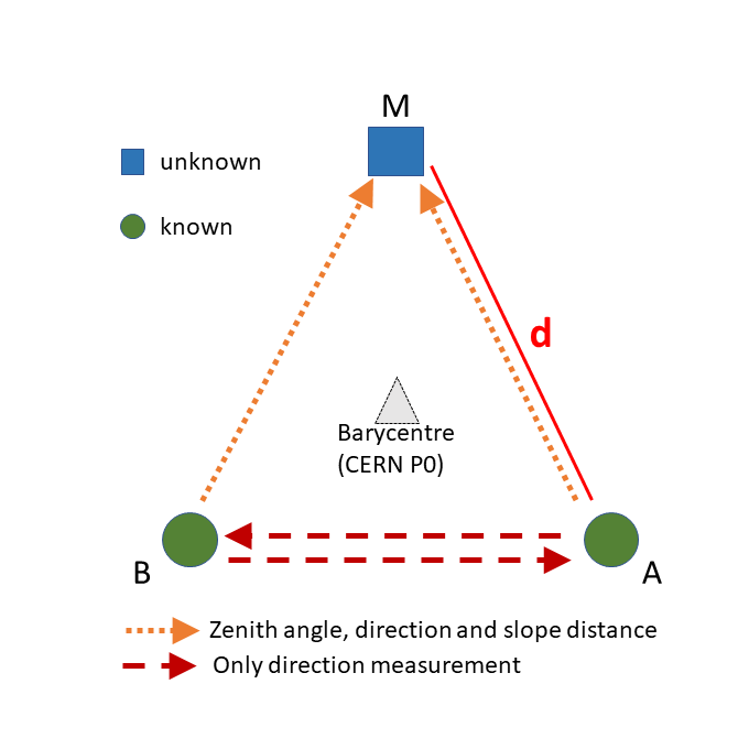 | Warning (figure 1 in the 2020 article): In the paper publised in 2020 in the Journal of Surveying Engineering, point P1 and P2 have to be permuted to correctly use the datasets proposed on this webpage. The figure located on this webpage is the correct one (P1=A, P2=B). Warning (DMS value for latitude of point P0): In the paper publised in 2020 in the Journal of Surveying Engineering, the correct DMS value for the latitude of point P0 is 46°13′56.21′′ N. The principal point P0 at CERN is the barycentre of all our test networks. Geodetic latitude and longitude for point P0 are 51.3692 and 6.72124 grads with respect to the CERN Geodetic Reference Frame (CGRF) (the reference frame tied to the reference IAG GRS 80 ellipsoid). For P0, the ellipsoidal height is defined to be 433.65921 m and the geoidal undulation is zero. |
In order to generate coordinates for our test networks, we defined a P0 point which have the same definition in ERTF89 than the CERN P0 point in the CGRF: same values for latitude, longitude and elipsoidal height with no geoidal undulation with respect to IAG GRS 80 ellipsoid. The following table summarizes the ETRF89 coordinates of this P0 point:
| Ellipsoidal coordinates (wrt. IAG GRS80) | Cartesian coordinates | ||||
| Latitude | 51.3692 grads | 46°13′56.21′′ N | X | 4395400.3638 m | |
| Longitude | 6.72124 grads | 006°02′56.82′′ E | Y | 465785.0567 m | |
| Ellipsoidal height | 433.65921 m | Z | 4583458.2260 m | ||
The CoMeT application is used to generate measurements in all the test networks. A Gaussian error is added to the computed theoretical observation values, in a particular way explained in an article (in french) of the revue XYZ (XYZ n°158 - 2018).
The main parameters used for the generation and the processing of the measurements are:
| Refraction coefficient | none |
| Standard deviation (angle measurements) | 0.3 mgrad |
| Standard deviation (slope distance) | 5 mm |
Coordinates and measurements datasets
Point coordinates (ETRS89 geodetic Cartesian coordinates) and generated observations between points for each network side length are available:
Zip file containing all the datasets (CSV format): Datasets.zip For each network side length d, the ETRF89 geodetic Cartesian coordinates for points A,B and M are compiled in a file named d_coord.csv For each network side length d, the direction (grads), zenital angle (grads) and slope distance (meters) are compiled in a file named d_meas.csv
Webpage summarizing the datasets: datasets webpage
Evaluated network adjustment tools
CoMeT - Compensation de Mesures Topographiques (version: 2017.02.14)
Original results from the 2020 article
comet.esgt.cnam.fr
Direct use of the ETRF89 coordinates / IAG GRS80 elipsoid
2D and 1D differences are obtained by the computation of the coordinates of the adjusted point M in a local geodetic system with respect to the IAG GRS80 reference ellipsoid, with the theoretical point M at the origin.
LGC - Logiciel Général de Compensation (version: 2.01.00)
Original results from the 2020 article
ETRS89 Cartesian coordinates converted into Cartesian CCS (Cern Coordinate System) system.
Ellipsoidal heights converted to Z-coordinates using the CERN Spherical vertical datum.
LGC provides CCS coordinates of point M, which are converted back to ETRS89 Cartesian coordinates.
2D and 1D differences are obtained by the computation of the coordinates of the adjusted point M in a local geodetic system with respect to the IAG GRS80 reference ellipsoid, with the theoretical point M at the origin.
Trinet+ (version: 7.2)
Original results from the 2020 article
ETRS89 Cartesian coordinates converted to CH1903+ Cartesian coordinates
Deflection of the vertical relative to Bessel 1841 ellipsoid computed from zero value deflection of the vertical on each point relative to the IAG GRS80 reference ellipsoid
Trinet+ provides adjusted topocentric coordinates of point M, which are converted back to ETRS89 Cartesian coordinates.
2D and 1D differences are obtained by the computation of the coordinates of the adjusted point M in a local geodetic system with respect to the IAG GRS80 reference ellipsoid, with the theoretical point M at the origin.
Geolab (version: 2001 and PX5 )
Added in May 2021
https://www.geolabsolutions.com
Direct use of the ETRF89 coordinates / IAG GRS80 elipsoid
2D and 1D differences are obtained by the computation of the coordinates of the adjusted point M in a local geodetic system with respect to the IAG GRS80 reference ellipsoid, with the theoretical point M at the origin.
Columbus (version: 4.6.2.41 )
Added in May 2021
http://bestfit.com
Direct use of the ETRF89 coordinates / IAG GRS80 elipsoid
2D and 1D differences are obtained by the computation of the coordinates of the adjusted point M in a local geodetic system with respect to the IAG GRS80 reference ellipsoid, with the theoretical point M at the origin.
Comp3D (version: 4.3.8)
Added in June 2021
© IGN, © Soldata
In the Comp3D application, 3D local coordinates are supposed to be expressed in terms of coordinates in a stereographic projection. The shape of the Earth is approximated by a local sphere which radius is computed from the latitude of the mean point of the network, using the Hayford 1909 ellipsoid. Therefore, at the mean point of the network, the projection plane is tangent to the Hayford 1909 ellipsoid and to the approximation sphere.
In order to process our test networks with the Comp3D application, we thus directly used the local coordinates of the points, assimilated as coordinates in a steregraphic projection which origin is the P0 point.
For practical reasons related to the operation of Comp3D, we used the approximated value of 46°14′ for the latitude of P0 with respect to the Hayford ellipsoid, yielding an Earth's Gaussian radius of curvature of about 6379277.698 m.
Local 3D adjusted coordinates are converted back into ETRF89 Cartesian coordinates.
2D and 1D differences are obtained by the computation of the coordinates of the adjusted point M in a local geodetic system with respect to the IAG GRS80 reference ellipsoid, with the theoretical point M at the origin.
Move3 (version: 4.5.1 x64 Demo )
Added in June 2021
https://move3software.com/
Direct use of the ETRF89 coordinates / IAG GRS80 elipsoid
2D and 1D differences are obtained by the computation of the coordinates of the adjusted point M in a local geodetic system with respect to the IAG GRS80 reference ellipsoid, with the theoretical point M at the origin.
JAG3D - Java Applied Geodesy 3D (version: 20210701)
Added in July 2021
https://software.applied-geodesy.org
-- Data processing and results kindly provided by Michal Lösler --
ETRF89 Cartesian geodetic coordinates are converted into local coordinates in the local geodetic system of point P0, with respect to the IAG GRS80 ellipsoid.
Version 20210701 introduces the possibility to use an ellipsoidal Earth model in addition to the spherical Earth model available in the previous versions.
This has been achieved by slightly changes in the functional model. The main difference is the derivation of the tilt parameters of the surface normal with respect to the principal point: current version uses trigonometric functions instead of approximation using the equation of the "circular sector" in the former one.
Results obtained using both approches are shown here.
In the ellipsoidal approch (JAG3D (ELIP)), the local ellipsoidal Earth model is used in JAG3D, and the IAG GRS80 ellipsoid is selected. Ellipsoidal coordinates of point P0 with respect to the IAG GRS80 ellipsoid are inputed as reference latitude, longitude and ellipsoidal height in JAG3D.
In the spherical approch (JAG3D (SPHE)), an Earth radius value of about 6379022.27154 m is used, which corresponds to the Earth's Gaussian radius of curvature at the latitude of the P0 point, with respect to the IAG GRS80 ellipsoid. The ellipsoidal height of the P0 point, 433.6592m, with respect to the IAG GRS80 ellipsoid, is used as the reference height in the application.
Adjusted local 3D coordinates are converted back into ETRF89 Cartesian coordinates.
2D and 1D differences are obtained by the computation of the coordinates of the adjusted point M in a local geodetic system with respect to the IAG GRS80 reference ellipsoid, with the theoretical point M at the origin.
Star*Net (version: 10 v10.0.15.974 x64 Demo )
Added in June 2021
https://www.microsurvey.com/products/starnet/
Direct use of the ETRF89 coordinates / IAG GRS80 elipsoid
2D and 1D differences are obtained by the computation of the coordinates of the adjusted point M in a local geodetic system with respect to the IAG GRS80 reference ellipsoid, with the theoretical point M at the origin.
Interactive access to the results
An interactive tool showing the main results: estimated variance factor, 2D horizontal distance between estimated and theoretical coordinates and coordinate difference in the vertical component


